Search This Blog

Showing posts with label Product Development Cycle. Show all posts

Tuesday, May 3, 2011

A Basic Approach to QFD

7.2 The QFD Approach
There are several approaches to QFD; each of these approaches makes use of matrices to organize and relate pieces of data to each other.  Many times these matrices are combined to form a basic QFD tool called a “House of Quality”.
The basic approach used here is conceptually similar to the practice followed by most American manufacturing companies. In QFD we typically follow the flow as defined in Figure 7-2.  We start with customer requirements, which may be loosely stated qualitative items such as: looks good, easy to use, works well, feels good, safe, comfortable, lasts long, luxurious or specifically defined requirements. These are important to the customer, but do not represent a product definition. In order to implement a product system engineers need to convert these vague customer requirements into actionable internal company requirements, which we call design requirements. These are generally global product characteristics such that if properly executed the product will satisfy the customer requirements.


 Figure 7-2 The typical flow of applying QFD has five steps
Products are not usually developed at this glo­bal level, but rather at the system, sub-system or part level. The global design require­ments must then be translated into specific product design, company infrastructure and capital investment requirements. Every product has several critical characteristics that determine how good a product fulfills its intended functions. The QFD process allows one to track these critical characteristics throughout the development process. Next determine the required manufacturing operations. This stage is often con­strained by previous capital in­vestment. Development organizations usually do not want to build a new factory or install a new line of equipment to produce a new product ver­sion and this often constrains product design and production methods.
Within the defined operating constraints determine which manufacturing operations are most critical to creating the desired critical product and part characteristics, as well as the process parameters of those operations which are most influential. Think of these process parameters as the knobs or dials of the manufacturing operation that are controllable. The manufacturing operations are then deployed into production requirements, which are the entire set of procedures and practices that enable the production system to build products that ultimately satisfy customer requirements.
These operating procedures determine how the factory operates the manufacturing processes to consistently produce the required critical product/part characteristics. They include a number of ̏soft" issues such as inspection and Statistical Process Control (SPC) plans, preventive maintenance programs, operator instructions and training, as well as identifying the need for mistake proofing devices for preventing inadvertent operator errors
The hierarchical approach described above is not unlike the approach taken for years with varying degrees of success. The problem is that some of the translations are not made properly. There are several key reasons for these improper translations that are the result of the structure of large organizations and the complexity of the product development process.
7.3 Hierarchical Matrices and QFD Phases
There are several approaches to the implementation of QFD.  The QFD method presented here follows the approach taught by the American Supplier Institute (ASI) based upon the “House of Quality” structure. The basic matrix structure consists of various types of matrix and table sections (or “rooms”) linked together to form what has been termed the “House of Quality”.  The ASI approach implements a four phase approach with matrices representing the important characteristics for each phase.  Figure 7-3 illustrates the four phases and how the key characteristics of each phase are deployed to the next phase of development.

Figure 7-3 The four phases of QFD consist of four linked matrices called Quality Tables.

The four phase approach results in a hierarchical series of matrices where each individual matrix is called a quality table and are numbered, e.g. QT-1 thru QT-4.  In the four phase approach a team determines the relationships between customer requirements and product design requirements.  The product design requirements are then deployed to the QT-2 matrix. In QT-2, the team determines the relationships between design requirements and product design.  The product design is then deployed to the QT-3 matrix to determine the relationships between product design and process design. The process design is then deployed to QT-4 matrix to determine the relationship between process design and manufacturing operations.

The four phase hierarchical series of matrices when completed links the customer requirements all the way to the manufacturing operations.   Thus as the manufacturing operations meet their deployed requirements then indirectly the customer requirements are being satisfied.  Therefore the resulting product or system is Customer Driven.

Tuesday, August 31, 2010

Definitions of Systems and Systems Engineering

Now that we have taken what is hopefully is a fresh look at what systems engineers do let’s back up and look at some traditional definitions of a system and systems engineering. I have used these definitions for so long that I have forgotten their original sources and I apologize. There are almost as many definitions of a system and of systems engineering as there are systems engineers so I prefer not to put much emphasis on these definitions but include them for completeness and to make a critical point about defining things with text based definitions.

One source says a system is a collection of objects working together to produce something greater. A system can be tangible, like a rocket or a communications network, or intangible like a computer software program or any combination of tangible and intangible. A system is composed of unique elements and the relationships between these elements. The elements in a system can be highly hierarchical or essentially flat like a network, or again any combination of hierarchical and flat. A system has the further property that it can be unbounded; each system is invariably a part of a still larger system. This characteristic of a system leads to a complication in definitions. Some systems engineers use names like “system of systems” to account for certain types of systems; often those involving complex interactions with humans. From a semantics point of view a term like “system of systems” makes no sense as it’s equivalent to saying a “universe of universes”; but if such terms communicate something important to those working on the development of certain types of systems then the terms serve a useful purpose. Also we have to remember that sometimes customers invent new terms and we have to use them even if we don’t agree. It usually isn’t worth trying to be “virtuous and pure” over such issues.

One pragmatic way to define a system is that it is the design element at the top of the hierarchy being developed by a systems engineer’s team. Thus it’s the collective name of that design element. The system being developed may be part of a larger system but the development team only has to be concerned with the requirements for their system and the interfaces of their system with the larger system, not with what to call the larger system.

Eberhardt Rechtin, in his book “Systems Architecting: Creating & Building Complex Systems”, says the essence of systems engineering is structuring. Structuring means bringing form to function or converting the partially formed ideas of a customer into a workable model. The key techniques are balancing the needs, fitting the interfaces and compromising among the extremes.

Others describe systems engineering as both a technical and management process. One source says “it is a discipline that ties together all aspects of a program to assure that individual parts, assemblies, subsystems, support equipment, and associated operational equipment will effectively function as intended in the operational environment”. One of my favorite definitions is from a U.S. Navy web site.  It says systems engineering “is a logical sequence of highly interactive and iterative activities and decisions transforming operational needs into a description of system performance parameters as well as a preferred system configuration.”  This definition is amusing because it is exactly correct in saying systems engineering is highly interactive and iterative but the reality is that it is logical only to a highly experienced system engineer. Something that is highly interactive and iterative hardly appears logical to someone not intimately familiar with it.

Comparing these definitions with the four tasks for systems engineers defined in Figure 3-3 of the previous post shows that the definitions do not capture all that is implied in the four tasks. From the definitions would a young engineer realize that a system engineer has a role in planning and scheduling a development program; or in verifying the performance of a system design? If this chapter started with the standard definitions of a system and systems engineering would a logical path to the four systems engineering tasks have been easily found? If just the five text words had been used to define the product development cycle instead of the labeled graphical model would it have raised the question of whether the four tasks are rigidly sequential or allowed to overlap in time? Perhaps, but not as easily as it is starting with the graphical model of product development as the five simple sequential tasks or phases of define, design, build, test and produce.

Graphical Models vs. Textual Models

There is a profound principle in the last paragraph above. Textual descriptions of complex ideas are often incomplete and very often lead to different readers having different understandings of the ideas. Labeled graphical models of complex ideas are less ambiguous. This is a critical point for systems engineers to remember and use in their work. Look back at the second figure in the previous post. The thin solid arrows indicate that the outputs of a task are the inputs to the next task. In the development of complex systems each task typically involves different teams. Therefore it is critical that the outputs of one task be easily understood and unambiguous to the teams working on the following tasks. Labeled graphical models are much easier to understand and less ambiguous than textual descriptions for most engineers.

Think back to the “Craftsman” model of product development defined earlier that was successfully used for centuries for simple products. The output documentation from the chief engineer and his/her team was engineering drawings. The workers and managers in the factories responsible for producing the products could clearly understand and use these engineering drawings. Imagine if the chief engineer and his team submitted textual descriptions of their product design to the factories.

Another example of a labeled graphical model being superior to textual descriptions is maps. Imagine going on a driving vacation through your country using just a textual description of the location of towns and the roads connecting them. Just keeping track of where you are with respect to the textual descriptions would become a time consuming task. This is why maps became the standard model for describing geography centuries ago.

One of the reasons development of complex systems often failed to achieve the planned schedule and budget after systems engineering was introduced in the 1950s and 1960s to address  the complexity of modern systems was that some of the documentation produced by systems engineers and passed to design engineers was textual descriptions rather than labeled graphical models. Unfortunately this practice continued when concurrent engineering was introduced and continues today for many organizations. One of the primary objectives of this book is to convince systems engineers to use labeled graphical models wherever possible and avoid textual models wherever a graphical model can be used instead. This is one of the keys to achieving faster and lower cost systems engineering, as will be explained in a later article.

System Engineering and Design Engineering

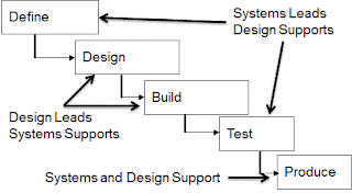
Accompanying the introduction of systems engineering was the practice of distinguishing between systems engineers and design engineers. It was natural to label the engineers doing the systems engineering work as system engineers. Since functional engineering organizations were typically broken down into mechanical departments, electrical departments or some similar differentiation it was natural to set up systems engineering departments for the systems engineers. This is unfortunate because all engineers do some systems engineering work and all engineers do some design engineering work.  It is true that systems engineering has become a specialty just like other specialties of design engineering and that systems engineers use some processes that are fundamentally different than design engineers. We must keep the various specialties but perhaps we could change the term design engineer. This might help remove some of the undesirable barriers that creep into our organizations that inhibit effective communications. However, using the term design engineer helps define the different rolls of system engineers and the various specialties. Let’s use the diagram from Figure 3-4 to help define the traditional roles and responsibilities of systems engineers and design engineers. The result is shown in Figure 3-5.


Figure 3-5 The traditional roles of system engineers and design engineers involve responsibilities within each development phase.

 From Figure 3-5 and the description of what takes place during each task or phase we can further define the traditional differentiation between systems engineers and design engineers in simple terms as follows:
·         Systems Engineers Determine
o   What’s to be built
o   How it’s supposed to function
o   Whether it meets its requirements
·         Design Engineers
o   Determine how it’s to be built
o   Make it  operate (integration & test)

It is critical to understand that both systems engineers and design engineers are involved in all five phases as shown in Figure 3-5. To further define the role of systems engineers it helps to look at how they are integrated into a typical organization. That is the subject of the next article.

Thursday, August 26, 2010

Introduction to Systems Engineering

Systems engineering is defined in many texts. Rather than repeat the standard definitions at this time it is helpful to define these terms in the simplest possible manner. The reason is that having very simple definitions helps us to consider things from a fundamental point of view, which makes it easier to come up with new insights. Later traditional definitions are presented and comparing the two may give new insights. New insights are needed in order to understand new methods and, eventually, to develop improved methods. This chapter, presented in several articles, defines four fundamental tasks that systems engineers perform, provides definitions of systems engineering, compares the rolls of systems and design engineers and shows how systems engineers fit in a modern product development organization. The four systems engineering tasks are deliberately defined before defining systems engineering or systems engineering processes. Although this seems out of order it helps take a fresh look at systems engineering methods. To set the stage for defining the four tasks of systems engineering we look at the overall product development process or development cycle as it is usually called.
The Product Development Cycle
In the exercises at the end of the last post the reader was asked to define the product development cycle in simple terms a grandmother would understand, assuming the grandmother is not a systems engineer. The purpose of this question is to make the reader think about the fundamental tasks that comprise product development. Sometimes people get into the detail of their work to the point they lose sight of the fundamentals of what they are doing. Figure 3-1 illustrates what the reader might have said.


Figure 3-1 Product development consists of five tasks, or phases, at a fundamental level.

Product development organizations typically define the product development cycle in a much more complex diagram, or set of diagrams, that describe the tasks to be performed in much more detail than shown in Figure 3-1. However, it is important to step back and look at the fundamental tasks, or phases if you prefer, in as simple of terms as possible if we intend to improve the overall process. Starting with the simple flow chart in Figure 3-1 we define the work that systems engineering encompasses, again in simple terms, because our objective is to seek better methods for systems engineering. Note that Figure 3-1 leaves out the object of the verbs. This forces us to think about what it is that we are defining, designing, etc. For example, it’s necessary to define both the product and the program for developing the product. Decisions must be made about what will be designed, what will be tested and what will be produced. These decisions are product dependent and involve systems engineers if only as advisors. We can add some of the top level inputs and outputs of each step in Figure 3-1 as we think about what it is that we are defining, designing, etc. A result for one type of product might look like Figure 3-2.
The tasks shown are performed by a variety of managers, technicians, and engineers; systems engineers, design engineers, test engineers, etc. We seek to define just the tasks performed by systems engineers. Actually systems engineers are involved in all five tasks to some extent. Typically systems engineers are responsible for the specifications and plans that are produced in the “Define” task and contribute to or oversee work in the other four tasks. With these roles in mind we can think about the tasks the systems engineers perform. Recall that here nontraditional terminology is used at to describe the systems engineering work.

Figure 3-2 The outputs of a fundamental product development task are the inputs of the next task

Four Fundamental Tasks for Systems Engineers
A simple but useful terminology for defining systems engineering work is shown in Figure 3-3.

Figure 3-3 Four fundamental tasks performed by systems engineers during the product development cycle.

The four tasks listed in Figure 3-3 are not the only way to define systems engineering tasks, or are these are a complete description, but these four tasks help us understand the fundamentals, if we allow for some flexibility in our definitions. This becomes apparent as we examine in more detail the four tasks in later chapters.
Notice that the first three systems engineering tasks are shown as overlapping in time rather than being sequential in time. This is because these tasks should overlap in time. This is a good point to introduce one complexity in the fundamental task list shown in Figure 3-1, then we can return to defining systems engineering.
Progressive Freeze of Product Development
The product development tasks should not be rigidly sequential but should allow for some overlap in time, as indicated in Figure 3-4.


Figure 3-4   The fundamental product development tasks should be allowed to overlap in time.

Often major product development tasks, or phases, are gated by milestone reviews. This implies that all work must be completed on one phase of the product development before work can start on the next phase. It is not good practice to demand rigid adherence to the gating process. A better approach is to allow some work to begin as soon as the information needed for initiating the task is available. This is called progressive freeze, as discussed in previous  articles, and it adds flexibility to the work that offers benefits that outweigh the small additional risks incurred.
Progressive freeze is practiced by freezing an element of the engineering work, when the risk of freezing the work is acceptable and allowing work on the next phase to begin before the next milestone review. Engineering judgment is used to determine when the risk is acceptable that the continuing work on other elements of the development work won’t change the results of the frozen work element.
A couple of examples help understand the progressive freeze concept. Consider a radio frequency (RF) sensor. Freeze the antenna architecture when the gain, antenna configuration and interfaces are determined; initiate the antenna design in parallel with other subsystem architecture trades. Hold a system design review (SDR) or architecture review, if required, when all subsystem architectures are frozen. Second, consider an infrared sensor. The telescope architecture can be frozen when the aperture size, the form, the optical subsystem f/# and interfaces are determined. The telescope design can then proceed while the focal plane, electronics and cooling architecture trades continue.

There are several benefits from beginning the design early for the RF antenna or the telescope in these two examples. The biggest is the flexibility in scheduling the skilled antenna and telescope designers. Critical skills such as these are often in high demand on several programs. By enabling early starts of the design work involving critical skills it increases the total time period for the design work to be accomplished without impacting the program schedule and helps avoid program delays due to the unavailability of critical skills.

A second benefit is that progressive freeze facilitates sequencing design decisions throughout a design phase. Product development involves thousands of decisions in each phase of the work. Delaying decisions until just before major design reviews complicates decision management to the point that the quality of the work can be threatened. Making decisions as soon as risk allows spreads the decisions throughout a development phase and makes decision management easier. We will return to this issue in a later chapter where we explore design decision management in more detail.

 Another benefit is that should a problem arise in the design that impacts other architecture the architecture changes can be made easily if these trades are still underway. For example, suppose the RF antenna designer discovers that the desired gain margin cannot be achieved within the constraints defined in the architecture trades. If the other trades are still underway it is much easier to decide how to accommodate the problem. It may be that a larger envelope is available or it may be that the lower gain is acceptable with tighter control of noise figure in the amplifier electronics. Finally, allowing more time for the designers to work on a design element may result in a better design. Sometimes engineers need to set work aside for a short period while they mull over a difficult design issue. Sometimes unforeseen difficulties arise in design and having extra time to work out these difficulties helps avoid program delays.